Monster
iCruze
displays
A nice 2 x 20 backlit surplus display very useful
for DIY projects
As used by Time Nuts
Last update: 11-04-2010
This page will be updated as I get
new data.
Some history:
Around
2005
an audiophiles (or
should I say Audiophools?)
accessories company called Monster
Cable Products Inc, launched an innovative system to connect
an iPod to the car audio system, making the carís radio think
the iPod was a CD changer and thus allowing to control the
iPod from the radio controls, including the mounted on the
steering wheel, if any. The
system had an optional $100 display
(which is what this is all about) which shows the song title
and artist name, as stored in the iPod files.
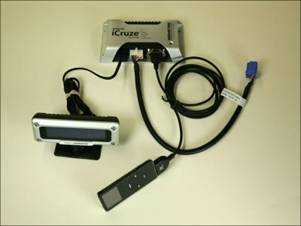
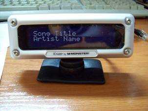
An iCruze complete system The display (the text is simulated)
For some reason that I ignore, but
probably a sales fiasco since the basic system was sold by
some $200, this nice system became a kind of Ford Edsel. If you try to search for any
reference about it in the Monster web site as I did (http://www.monstercable.com)
you wonít find anything, as if the system had never
existed (anyway internet has its memories and yes, it did
exist).
The first time I knew about those displays was in the Time-Nuts list. One member of this list, Didier Juges KO4BB, had designed and built a standalone monitor for his Trimble Thunderbolt GPSDO (http://www.ko4bb.com/Timing/GPSMonitor/) and released his code under GPL. Other members of the list soon noticed that copies of Didierís monitor were being sold on eBay by a Chinese store. The owner of this store is Bob Mokia (http://myworld.ebay.com/fluke.l/), a well-known supplier of surplus time nuts goods. He got a batch of iCruze displays (probably the actual factory was on China), replaced the microcontroller board with one of his own, programmed it with the Didierís code and made some changes to the original cable.
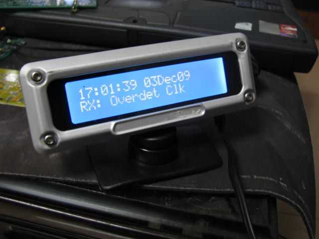
Didierís Thunderbolt monitor in the iCruze display, as sold by fluke.l
Another member of the list, Arthur Dent, bought one of Bobís monitors for his Thunderbolt. He removed the case and integrated the electronics and the bezel on his own cabinet. He was the one who discovered the gadgetís origin and found that some outlets in Amazon were dumping them at $2 each, so he also bought one hoping that he could use it someday.
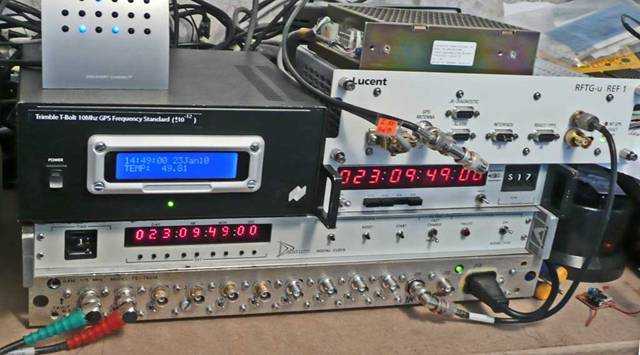
The monitor integrated in Arthur's GPSDO, among other of his Time Nutsí stuff
I found about the existence of the cheap sources through Arthur, who kindly sent me a picture showing the internals of the original unit and the one modified by Bob. It can be seen that the original PCB holding the microcontroller was replaced by a new one with the component side reversed. The reason for replacing the board is because Didierís code runs in another family of micros and it seems that Bob took the hardware way instead of porting Bobís 8051 code to the Atmel TINY micro. Another reason could be that the existing micro lacks the resources needed for the task.
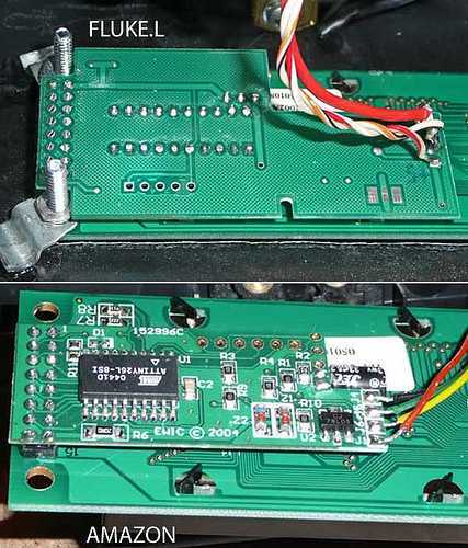
Pictures showing the inside. The original is at the bottom and the modified one at top
I
bought some of the original displays from an Amazon
seller. I had previously made before some gadgets with
LCDs, mainly Frequency Counters and Digital Dials for
Boatanchor radios and I had found that the most
difficult thing to properly finish the enclosure was the
cutout for the display or the lack of a suitable bezel.
These displays have a nice
bezel and even in some cases everything could be
included into the original cabinet in a fashion as Bob
did with the Thunderbolt monitor.
After
reading
the thread about this subject in the Time-Nuts list I
played with the idea of recycling the whole gadget
without removing or replacing the microcontroller board.
For some uses just
reprogramming the micro could be enough; or even
innecessary. Imagine that
the toy is just a serial 20 x 2 ASCII terminal, so that
you can send the data you wish to display just to the
current cable. Your code
would have to send the data to a kind of serial port,
instead of to a display driving routine and the display
could be located some distance away, which could be
advantageous in some cases .
Later
I received several emails from more list members who had
also bought some displays and wanted information. This is why I started this
page.
I tried to get as much info as I could and began to reverse engineer the gadget. After capturing the schematics and once seen how it was powered (it was an automotive application, but I didnít know what was on the other side), I applied 12 volts on the input cable between the red and black wires. The backlight turned on but nothing appeared on the screen. I began to probe everything with a scope and the only activity that I found was a pulse train on the yellow wire, with a negative going pulse of about 2 ms every 1.6 s; maybe it is trying to wake up the other side.

This is the schematic, it can be downloades in
both Eagle.sch and .png formats

